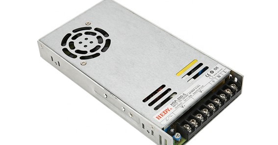
As you may know, a power supply circuit is one of the most important in studying electronics. As an electronics student, almost everyone wants to do well. Nothing beats the feeling of accomplishment when you finish your first power supply design, test it, and find that it works perfectly.
Alright!
When you design a 5v power supply circuit, you start with a well-drawn generic block diagram. Designed parts of the circuit are put together at the end to make a complete circuit that works.
The general block diagram for this project is shown below. It’s very easy to do. The following is a list of the four basic components:
- Transformers
- The Rectifier’s Circuit
- Also, there is the Filter.
- The Regulator
First, I’ll explain the basics of each block. Then, we’ll start making things. You should first figure out what each block is in charge of. Let’s start by going through each part one at a time.
The input transistor:
Transformers are machines that use the law of energy exchange to change the voltage level. Why do we need to plan the supply chain, anyway?
Depending on where you live, the AC that comes to your home has either 220 or 120 volts (RMS). The input transformer must step down the AC that comes into a lower voltage close to 5V. (DC). The 5V DC that other blocks need comes from this lower level.
Transformers can be used to change the level of AC voltage while keeping the same amount of power coming in and going out. Be careful when playing around with this thing.
Your use of the power grid can be very dangerous. Don’t use your bare hands or tools that aren’t very good to touch any of the terminals. Use a reliable non-contact voltage tester to figure out which wire on the transformer is the live one.
The rectifier’s circuit:
I don’t think the transformer just lowered the voltage to 5 volts of direct current by mistake (DC). I’m sorry, but you and I were both wrong. Even though the voltage is lower, it is still AC. A proper rectifier circuit is required in order to convert it to DC.
In a rectifier circuit, the way the diodes are set up makes it possible to change AC voltage to DC voltage. Without a rectifier circuit, you can’t get the 5V DC output you need. This circuit can be made with just four diodes, but it is easier to use integrated packages. You’ll see how we put everything together in the next parts.
There are two main kinds of rectifier circuits: half-wave and full-wave. On the other hand, we want the complete rectifier because it uses less energy than the first.
The Filter is: –
In the real world of electronics, nothing is perfect. Unfortunately, the rectifier circuit can only change AC to DC, not DC to DC. The power that comes out of the rectifier is called “pulsating DC.” It would help if you didn’t use this pulsing DC to power up sensitive electronics.
Because of this, the corrected DC is not very smooth and has ripples. The Filter’s job is to get rid of these ripples and ensure the voltage is stable enough to control. A capacitor filter is used to get rid of distortion in a signal or to turn pulsing DC into pure DC. In general, DC voltage must have less than 10 percent waves to be completely controlled.
For us, the capacitor is the best Filter. You may have heard that a capacitor is a way to store electricity. It works best as a filter, though. We chose it because it was the cheapest for our basic 5V power supply.
Regulator: –
A linear integrated circuit is used in regulators to keep the output voltage constant (LII). Voltage control is important if you want to keep the output voltage constant. There is always a need for an output voltage that doesn’t depend on the load. With the Regulator IC, the output voltage is not only unaffected by changes in the load but also by changes in the line voltage.
A regulator is an integrated circuit that keeps the output voltage steady even when the voltage changes. I hope you’ve learned how to lay out a power supply.